One of the greatest technological marvels in aviation is used every day, all around the world. It allows aircraft to descend from a safe altitude and navigate directly to the threshold of a runway safely, without any outside visual reference at all. It’s called the Instrument Landing System, or ILS.
The ILS, or instrument landing system, is a collection of navigational aids that directs the aircraft to the runway. It is an example of a precision instrument approach procedure, meaning that it provides the pilot with both lateral and vertical guidance.
Precision VS Non-Precision Approaches
Instrument approach procedures, or IAPs, come in a variety of forms. The two main types are precision approaches (PA) and non-precision approaches (NPA).
The distinction between them is that precision approaches give the pilot an indication of their vertical location. Like the VASI and PAPI lights mounted next to a runway tell visual pilots whether they are too high or too low, the glide slope on a precision approach tells the pilot the same thing.
In contrast, the most basic types of non-precision approaches have a navigational aid, like a VOR or NDB, at the airport. The pilot can navigate to this NAVAID directly.
The IAP chart will depict the final approach course to that marker. A simple VOR approach would require the pilot to fly to the station, fly outbound on a radial, make a course reversal turn back to the station, and then descend on that course to the Minimum Descent Altitude (MDA).
The courses and altitudes used would all depend on obstacles in the area and the location of the runway. Generally, the pilot cannot descend below about 600 feet AGL on the final approach without seeing the airport.

The problems with a non-precision approach, like the one described above, are many. With such a high MDA, the aircraft must make a steep and perhaps unstabilized approach. At such an altitude, even a moderately low overcast can make it impossible to see the runway, resulting in a missed approach or go-around.
The precision approach fixes these problems by providing more accurate guidance to the runway. Instead of the NAVAID being general-purpose and located anywhere at the airport, a precision approach directs the pilot to a specific runway threshold.
Additionally, the glideslope is positioned to direct the flight to the touchdown zone of the runway. By providing both lateral and vertical guidance, instrument landing systems can be so precise that they can allow certain aircraft to land in completely instrument conditions.
Minimum Descent Altitude VS Decision Height
One fundamental difference between the NPA and PA is the way the aircraft descends. In a non-precision approach, the plane is leveled off and stable at or above the minimum descent altitude (MDA).
It cannot go below that altitude unless the runway environment is in sight, and the flight visibility is above the minimums published on the approach chart.
An aircraft stabilized on a glideslope is in a descent already. Instead of having an MDA, the pilot has a decision height (DH). At the DH, the pilot must determine if the runway environment is in sight or not.
If it is not, a missed approach must be initiated. The term decision altitude (DA) also applies, the height being above ground and the altitude being above sea level.
Categories of ILS
As technology has improved, so has the ILS systems used by major airports and aircraft. For each better type of approach, a lower DH can be utilized.
Standard ILS approaches are referred to as Category 1 (Cat 1) approaches, and they usually allow the aircraft to descend to about 200 feet above the touchdown zone without any outside reference.

With specialized equipment and crew training, Category 2 and 3 approaches allow even lower DHs. Most Cat 2 approaches have a DH of around 100 feet AGL, while Cat 3 approaches are as little as zero.
It’s important to reiterate that Cat 2 and Cat 3 ILS approaches require special equipment and training. For a 0/0 Cat 3 approach, the aircraft must be equipped with autoland functions.
What Makes ILS a “System”?
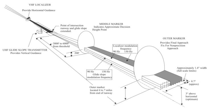
The instrument landing system is made up of three separate components. The components can be met in several different ways, but the system must have navigation, range, and visual parts.
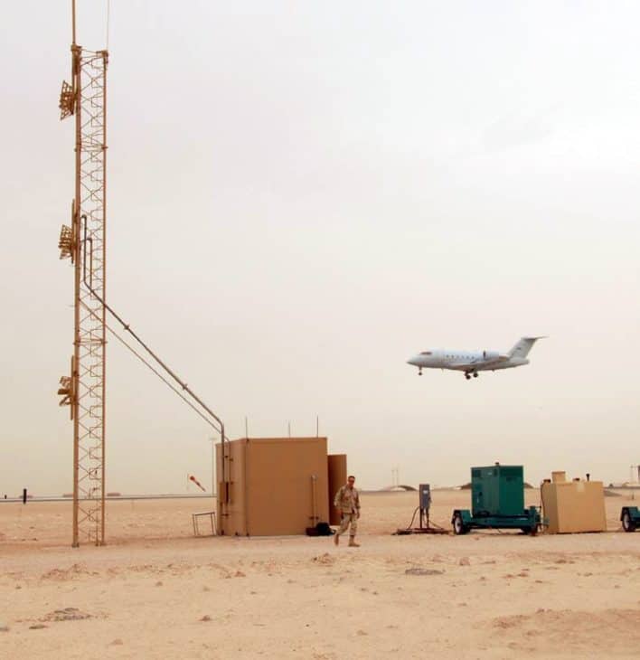
The navigational components of an ILS are the navigational signals directing the flight to the runway. The localizer provides the extended course line of the runway, so the pilot can see if they are left or right of course. The glideslope provides a vertical guide, telling them if they are too high or too low.

Range components tell the pilot how far they are from the runway. There are several ways to accomplish this. The original method was to install separate navigation aids, like low-powered NDBs called compass locators, along the course path.
When the pilot passed these beacons, the aircraft position was fixed. Some ILS installations also included the use of marker beacons, which flashed colored lights and morse code tones when the aircraft passed overhead. These too fixed the aircraft’s location. Both of these methods required extra equipment, making them more expensive installations for airports.
Alternatively, other navigation aids can be used in conjunction with the localizer course to tell the distance from the runway. For example, if the localizer has DME, a distance from the antenna can be displayed in the cockpit. The approach plate will then reference these DME distances as fixes along the course. If there are no substitutions, it will be published as an ILS/DME approach. Today, these fixes are usually replaced with GPS waypoints.
Yet another method to identify these fixes is to use an entirely different navigation aid. Many fixes are found by using a cross-radial off of a neighboring VOR. This requires a little more set up in the cockpit but is useful nonetheless.
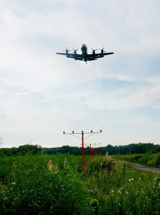
The final component of an ILS is the visual components on the runway. The goal is to make the runway as conspicuous as possible in low visibility situations. ALS, or approach light systems, come in many different forms, but all of them mark the runway threshold in a distinctive way.
Additionally, high-contrast runway markings and runway lighting are used. The higher the category of ILS, the more markings and lights are required.
How to Fly an ILS Approach
Despite sounding complex, the ILS is one of the most straightforward approaches to fly. The localizer frequency is tuned into the NAV1 receiver as a VOR would be. It is positively identified by audio morse code.
If this receiver is equipped with a glideslope indicator, it will automatically function. Likewise, marker beacons are always on, though for the audio they may have to be selected on the audio panel.
Intercepting and tracking a localizer is very similar to doing the same with a VOR radial. The difference is only that the localizer is much more sensitive. Also unlike a VOR, the localizer only produces one radial, so the setting of the OBS does not matter.
Range navigation will have to be arranged depending on the equipment in the aircraft and on the particular ILS approach. If an IFR-certified GPS is installed, the procedure should be loaded and armed. Fixes along the final approach course will then be identified.
Even if GPS is available, it’s wise to set up VOR cross radials, NDBs, or DME distances in advance should there be an equipment malfunction.
Once the approach is set up, the pilot flies inbound on the final approach course until the glideslope is intercepted. Then the pilot begins a stable descent at a predetermined rate based on the aircraft’s ground speed.
An easy way to quickly calculate the appropriate rate of descent in feet per minute (FPM) is to multiply your ground speed by five. If you are using a 90-knot approach speed, this makes for a 450 fpm descent.
The pilot maintains the descent while referencing the glideslope indicator, which will indicate if the aircraft is descending too quickly or slowly. The localizer is used to reference the runway centerline.
When the aircraft arrives at decision height, if the pilot can see a visual reference out the window, they continue to a normal landing. If nothing is seen, a missed approach must be initiated.
Importance of ILS on IFR Flights
Instrument landing systems are not installed at every airport. They are expensive and complex to maintain, so only airports with enough air traffic to support them will invest in them.
They are nearly always found at airports that regularly service air carriers. If a secondary airport has a lot of business jet traffic or training, they may too have one installed.
Non-precision approaches often serve general aviation airports. When flying to these secondary airports in instrument conditions, it’s vitally important to choose an alternate field for landing should conditions be worse than expected.
Knowing the location and conditions of the nearest airport with ILS is essential on any instrument flight. Even en route, these airports provide the best Plan B should you need to divert. They are easy to fly and precise, important factors when you are in trouble or an unfamiliar area. An ILS means that the flight can likely land in all but the worst visibility and overcast conditions.
There is a lot that goes into making an instrument landing system work, including specific operating parameters of the various components, and how to fly one with all of the multiple combinations of NAVAIDs. For more information, see Chapter 9 of the FAA’s Instrument Flying Handbook.
Related Posts
- Mayday Call: Diving Into This Vital Distress Signal
- Headwinds vs Tailwinds: What's the Difference for Pilots?
- What is a Bush Pilot and how to become one
About the Author